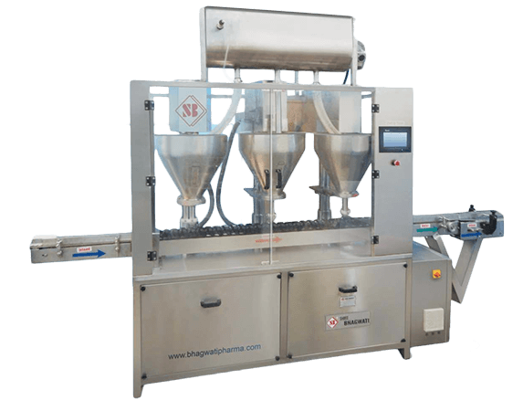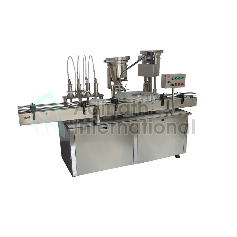

A Monoblock Filling Machine Is a Multi-Function Liquid Packaging System
A monoblock filling machine is a multi-function liquid packaging system. These machines contain all of the required machinery for filling, capping and labeling in one machine.
These systems need a control system to match the capper’s speed to the filler’s. They also need a mechanism that allows the capper to sustain a constant backlog of bottles during a filling run.
Variable Filling Capabilities
The Monoblock filling machine can be programmed to fill a wide variety of different containers. This flexibility is especially important if the product is sold in bulk. The containers may vary in shape, size and openings. They can also be a variety of different materials such as glass, plastic or wood.
This is one of the biggest advantages that a Monoblock filling machine has over other types of liquid filling machines. It is also the reason that many companies choose this type of equipment over other more complex systems.
Another key advantage that a Monoblock filling machine has is its ability to be easily reconfigured for different bottle sizes. This is important because the volume of liquid inside a container can be different for every bottle.
These differences can create a problem for a Monoblock filling machine if it is not configured correctly. This is a common problem with older types of equipment and can make the machine difficult to work on during maintenance or a breakdown.
The volume of a liquid product can also be determined by its packaging and the type of cap used. This can be an extremely important factor for a Monoblock filling machine, as the wrong cap could cause the liquid to leak or spill out of the container during transportation and storage.
If the product has a special cap that is not compatible with a standard screw cap, it can be impossible to use a Monoblock filling machine to fill it. The machine would have to be modified and reconfigured, which is not always possible.
Moreover, the container type can also have an impact on a Monoblock filling machine’s ability to be properly configured. The type of container can impact the nozzles that are used, the air flow and the overall system.
In addition, the machine’s capacity can be increased and decreased by adjusting the stroke length of the piston. This helps ensure that the filling process is accurate and does not have any unnecessary variations. Ultimately, this increases production and saves money by ensuring the correct product is packed in the right place at the right time.
Servo Motor-Controlled Motion
Liquid filling machines that have servo motors have the ability to produce more throughput than other types of automated systems. They are also less likely to cause product damage or to stall in operation.
Typically, a servo system is made up of three components: the motor, the controller and the drive. Each of these components has a specific role in the servo-system. The Vacuum Filling Machine motor is used to move a load; the servo controller is the brain of the servo-system and controls the motion; and the servo drive provides power to the motor and executes the motion.
A servo motor is controlled by sending an electrical pulse of variable width (PWM) through the control wire. The pulse determines the motor’s position. The motor then turns to the desired position. If the pulse is too short or the motor is in an incorrect position, an error signal is generated and corrected by the servo amplifier.
The servo controller uses this feedback to determine the actual position of the motor in comparison with the desired position. The servo controller then changes the signal to the drive to correct the error and complete the desired motion.
Another important factor to consider is the speed and acceleration of the servo motor. If the servo motor is not able to reach its target speed, it may stall. This issue is usually caused by a variety of factors, including overheating and weak bearings.
In addition, a servo motor’s voltage may fluctuate, causing it to operate poorly and not meet its specifications. It is essential to verify that the motor’s power supply is sufficient for its requirements. If the servo motor is overheating, the machine should be removed from production until it can be properly serviced.
A servo system must be designed to support the desired motion profile for each product. The motion profile is a mathematical equation that shows the distance, time and acceleration required to move the load to its final position.
In the case of a Monoblock filling machine, each servo motor is controlled by a servo controller that has a pre-programmed motion profile for each type of product. This allows the system to be adapted to a wide range of products with ease. This feature can also save valuable space in a production environment.
Starwheel
A star wheel is a common feature on many Monoblock filling machines and is used to index a pre-set number of bottles, vials or other containers into the machine for the next step in a packaging process. These indexing functions are a simple way to reduce labor costs and keep production running consistently.
The star wheel may be positioned on an automated handling line so that a container travelling down the handling line is received within a pocket as the star wheel rotates before being released at a defined point. The star wheel is driven by a servo motor so that each turn of the wheel delivers a bottle, vial or other container to the next packaging process.
Typically, the star wheel is comprised of a solid plastic wheel that contains pockets at given intervals to hold a container for which it has been designed. The pockets are machined into the wheel at certain points to accommodate a particular type of bottle or vial for which it has been designed.
In one embodiment of the present invention, a star wheel 100 is provided that comprises a disk with six pockets 102. Each pocket 102 is defined between two pairs of opposed fingers 104 which are rotatable about vertical axes to change their separation such that larger or smaller bottles can be accommodated in each pocket 102.
Each pair of opposing fingers 104 is stepped to have an upper portion of reduced outer radius bearing teeth 160 that engage with a pinion 162 that is rotatable about the central axis of the star wheel 100. The cog wheels 108,110 for each of the adjacent fingers 104 are meshed with a larger cog wheel 112 that is stepped to have an upper portion of smaller outer radius bearing teeth 162 that engage with a pinion 162 and is constrained to rotate about the central axis of the starwheel 100 by pins 164 received within circumferentially-extending slots 160.
In another embodiment of the present invention, a starwheel 110 is provided that comprises a disk with six corresponding recesses forming a Vacuum Filling Machine never-ending series around the periphery of the disk. Each of the recesses defines a pocket 102 that is defined between two opposing fingers 104, each of which is rotatable about vertical axes. The top 104T and bottom 104B fingers are separately rotatable about the vertical axes and the left and right fingers 104L,104R are rotated independently of each other.
PLC Control
A PLC (Programmable Logic Controller) is a computer that has been programmed with a program to perform various tasks. This program tells the PLC how to interact with factory equipment and human-facilitated inputs and outputs in order to provide a specific result.
PLCs have been around for decades and are the brain of many modern machines. They are also known for their simplicity and flexibility. They allow for a wide variety of functions, including adding and subtracting data, setting time and counting events, comparing information, etc.
The basic structure of a PLC features a central processing unit sandwiched between an input and output module. The input module is connected to factory equipment or other devices, such as sensors or keyboards, while the output module contains all the control components that operate a specific process.
Once the PLC is programmed, it enters a run mode and begins running the program. This process starts with the CPU reading data from the input module and checking its status. The CPU then executes the program written in relay-ladder logic or any other programming language.
After executing the program, the CPU sends all the program’s results to the output module. This information then determines which outputs to activate for a particular function. For instance, if the system needs to start a motor, then it will use the input module to determine which pilot light to turn on.
Another important feature of a PLC is its ability to be redundant, meaning that if one of the modules fails, the other can take over to prevent total or partial system shutdown. This can be particularly helpful for safety-critical processes, such as large hydraulic presses.
Inputs are the physical and visual signals that a PLC can receive in response to its program. These can include button pushes, switches, or sensors from a device like a keyboard, touch screen, remote, or card reader.
These can be set to control physical devices, such as starting motors, turning on lights, draining a valve or turning off a pump. They can also be used to control visual devices, such as projectors or printers.